Belt Calculations
Full details of the installation should be given to Fenner engineers for them to cross-check calculations and give the most economical and reliable belt recommendation. It is essential to have some information on the belt tensile requirement, belt length and width and the material being conveyed. Where the T1 figure (Tension at Drive Head) is known it should be used as the basis for initial belt selection. Otherwise, at least the following information should be given to enable this figure to be calculated:
1. Centre distance of conveyor (m)
2. Belt speed (m/s)
3. Peak loading (t/hr)
4. Belt width (mm)
5. Material carried
6. Angle of trough
7. Type of drive (number of drive pulleys, angle of the wrap, and whether steel or rubber lagged) and take-up arrangement (e.g. gravity, load sensed or fixed)
8. Net changes in elevation (rise or fall between loading point and delivery point in metres) and maximum gradient (degrees)
9. If known, details of idlers (the type of bearings, style of idlers, idler diameters, and pitch)
Alternatively, installed motor power can be used as a rough guide together with belt speed which must be provided. Actual power consumed whilst running fully laden is more relevant than installed power. Details of the material and general conditions are useful:
1. Size of material (maximum lump size, proportion fines to lumps)
2. Loading details (height of the drop, the direction of feed, etc.)
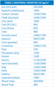
3. Condition of material (dry/wet, temperature, etc.)
4. Exact nature of the material (density, nature – sharp or rounded)
The correct belt selection must consider:
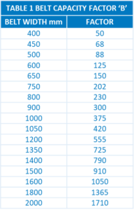
• Belt capacity
• Belt tensile strength
• Requirement due to load and conveyor structure
The Fenner formulae on these pages will give fairly accurate results through various other factors that can affect the total power requirement. For example in winter, additional power may be required to overcome initial friction in the idlers and transmission units. Poor chute design and seized idlers will also bring about the need for additional power, as well as promoting unnecessary belt wear. Similarly, if extensive skirt plates are fitted there may be a small additional power requirement, as there will on installations where a tripper exists. Wherever the above factors are likely to be significant Fenner should be contacted for advice.
Many similar formulae exist for calculating power requirements all of which are acceptable when correctly applied. It is important, however, that attempts are not made to transpose factors and constants from sources other than this brochure into the Fenner formulae, otherwise, inaccuracies are likely.
The power required to drive a conveyor is comprised of the sum of three separate power elements:
(a) Power to move the load horizontally.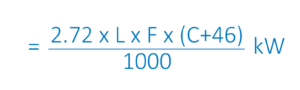 (b) Power to move the empty belt.
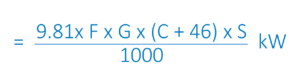
(c) Power to elevate the load.
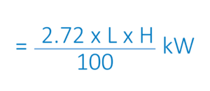
C = Centre distance (m)
F = Friction factor (see below)
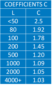
G = Inertia factor (Table 3)
H = Change in elevation (m)
L = Peak loading (t/hr)
S = Belt speed (m/s)
F – Normally 0.022 can be used but this may be reduced to 0.018 for well-engineered and maintained applications or increased up to 0.030 for poor conveyor installations.
where: The total power required: = (a)+(b)+(c)
However, if the load is to be carried downhill, (c) must be subtracted. Before the optimum belt type for a given installation can be determined, maximum tension (T1) must be established, and for this, the following information is necessary:
(1) Total power requirement (kW) (2) Belt width (mm) (3) Belt speed (m/s) (4) Take up details (5) Drive configuration.
The maximum tension for which the selected belt must cater can be calculated from the following formula:

K = Drive factor (Table 4)
P = Total power requirement (kW)
S = Belt speed (m/s)
Once this tension figure has been determined it must be divided by the belt width (metres) such that the tension can be expressed in kilonewtons per metre. The appropriate belt type can then be established. Belt selection is based upon the traditional 10:1 factor of safety which has proved satisfactory over many years of field experience. Nowadays, however, modern synthetic fibres, advanced belt designs, and improved joint efficiencies enable lower factors of safety to be considered in certain circumstances. Fenner will be pleased to advise on specific installations. Once the appropriate belt has been selected, drum diameters should be checked against the minimum recommended values.